
The Role of URDF in Developing Eco-Friendly Robots
How URDF Enables Eco-Friendly Robot Design: A Practitioner's Guide to Building Sustainability Into the File, Not Around It
You've sat in the meeting where sustainability comes up six weeks before manufacturing handoff. The CAD models are locked. The supplier quotes are signed. Someone mentions recycled aluminum, someone else mentions disassembly, and the room quietly agrees to "look at it for the next revision." This is how URDF eco-friendly robots stop being a design philosophy and become a marketing line. The problem is not commitment. It is sequencing. By the time environmental review enters most robotics workflows, the structural decisions that drive lifetime impact are already encoded in geometry that nobody wants to redo.
The Unified Robot Description Format (URDF) offers a different sequence. Because URDF is a text-based, declarative XML format that describes a robot as an explicit tree of links and joints — each with declared mass, inertia, geometry, and material references — it forces designers to commit to structural and material decisions in a constraint specification before CAD geometry is finalized. According to the ROS Wiki URDF tutorial, every link in a URDF must be defined as a discrete element with explicit physical properties. There is no rendering shortcut. There is no hidden geometry. That discipline is what makes the format useful for sustainable robot development.
This article shows how to use URDF's structure to drive material optimization, design for disassembly, simulation-based waste reduction, and a sustainability audit trail that survives engineering handoffs.
Table of Contents
- Why Sustainability Gets Retrofitted Into Robot Designs (And Why That Fails)
- How URDF's Declarative Structure Forces Environmental Decisions Upfront
- Material and Mass Optimization Inside the URDF File
- Designing for Disassembly Through URDF's Joint Grammar
- Simulation-Driven Waste Reduction with URDF and Physics Engines
- Embedding a Sustainability Audit Trail in URDF Metadata
- Environmental Tradeoffs URDF Forces You to Confront
- A URDF Eco-Design Workflow You Can Run on Your Next Robot
Why Sustainability Gets Retrofitted Into Robot Designs (And Why That Fails)
Most robot design pipelines start in CAD — SolidWorks, Fusion 360, CATIA — where geometry, fastener strategy, and material assignment happen in tightly coupled steps. The designer sketches a structural shape, the system computes mass from a generic density library, and the next revision builds on that geometry. By the time a sustainability review occurs (typically at manufacturing handoff or pilot build), the structural decisions that determine the majority of a robot's lifetime environmental impact are locked in. This sequencing is the root cause of failed sustainable robot development initiatives, and it's worth being specific about how it fails.

Welded and glued joints in CAD become permanent. When a designer fillets two parts into a continuous body or specifies adhesive bonding, the resulting geometry is not naturally decomposable. The CAD file shows one shape; the BOM shows two parts; the recycler can do nothing useful with either. Disassembly becomes destructive, and material recovery collapses to whatever survives shredding.
Material assignment is treated as cosmetic. In most CAD workflows, "material" is a dropdown choice from a rendering library, used to compute mass and produce realistic shading. The designer never sees a field that asks "where is this material sourced?" or "what is its embodied energy?" because no such field exists in the tool. Lifecycle implications are simply not part of the interface, so they are not part of the decision.
Sustainability review becomes sunk-cost negotiation. When environmental concerns surface late, every change costs CAD rework, simulation rerun, BOM revision, and supplier requalification. The path of least resistance is to ship the design and offset emissions later — or to claim improvements for the next generation. This is not a failure of intent. It is a failure of where in the pipeline the decision lives.
URDF inverts this sequence. Originally developed for ROS (Robot Operating System) to describe a robot's kinematic and dynamic structure for simulation and control, URDF is an XML-based format that requires every link, joint, mass, inertia, and material reference to be declared as a discrete field. The ROS Wiki tutorial on building a URDF model walks through exactly this: you cannot have a meaningful URDF without committing to specific values for these properties. The format is human-readable, version-controllable, and reviewable by anyone who can read XML — not just CAD seat holders.
The central argument of this article is structural: URDF's declarative grammar puts the environmental decisions you care about — mass, material, joint type, disassembly interface — into a specification that exists before CAD geometry. That specification is auditable. It is diffable. It can be reviewed by procurement, by sustainability leads, by supply chain analysts, by people who have never opened SolidWorks. A URDF-first workflow is the difference between green robotics design as a principle and as a practice. The remaining sections walk through how to make that practice operational on a real project.
How URDF's Declarative Structure Forces Environmental Decisions Upfront
URDF describes a robot as a tree of <link> and <joint> elements. Each link can carry an <inertial> block (mass, inertia tensor, center of mass), a <visual> block (geometry and material reference), and a <collision> block. Each joint declares its type (revolute, prismatic, fixed, continuous), parent and child links, axis, motion limits, and dynamics parameters such as damping and friction. The ROS Wiki and the Nav2 URDF setup guide document these conventions in detail. Every field is a commitment. You cannot leave mass blank in a URDF that drives meaningful simulation. You cannot bond two links without declaring the joint that connects them. The format makes structural choices explicit, and explicit choices are reviewable choices.
| Design Decision | Traditional CAD Workflow | URDF-First Workflow | Why URDF Surfaces Tradeoffs Earlier |
|---|---|---|---|
| Material assignment | Library selection for rendering; mass auto-calculated | Mass declared explicitly per link; material referenced by name | Designer commits to density before simulation, prompting material research |
| Joint connections | May be welded, glued, or filleted into one body | Every connection is an explicit <joint> element with type |
Each joint becomes a documented disassembly point |
| Mass and inertia | Computed from geometry and density library | Declared as <inertial> block per link |
Forces audit of every component's contribution to total mass |
| Iteration cost | Geometry rework; re-run CAD simulation | Edit XML field; re-run simulator | Material alternatives tested in minutes, not days |
| Reviewability | Requires CAD seat to inspect | Plain text; readable in any editor | Procurement and sustainability staff review without CAD training |
Text-based, declarative formats expose tradeoffs that CAD hides. In CAD, the visual continuity of geometry obscures decisions — a beautiful filleted shape looks intentional even when the fillet was a default. In URDF, every decision is a line of XML that someone wrote and someone else can question. This makes sustainability auditable by non-CAD specialists. A procurement officer can read the material reference. A sustainability lead can verify recycled-content claims against the supplier datasheet. A supply chain analyst can flag risky single-source dependencies. None of these reviewers needs a CAD license or training.
URDF turns sustainability from a downstream audit into an upstream design constraint. Every line of XML is a decision someone has to defend.
This aligns naturally with established environmental standards. ISO 14040 frames lifecycle assessment as a process that requires explicit data on materials, energy inputs, and end-of-life pathways. URDF's declarative structure produces the machine-readable substrate that LCA workflows need — link-by-link material and mass declarations, joint topology that maps to disassembly logic, version-controlled history of every change. CAD geometry rarely produces this cleanly because the data lives in proprietary binary formats and library lookups.
Be honest about the limit. URDF describes structure and physics, not chemistry or supply chain. A material name in URDF — "aluminum_6061" — does not automatically reveal embodied energy, recycled content percentage, or supplier certification. But it creates a hook to attach that data, and the hook is in the file the engineering team is already maintaining. That is the meaningful difference, and the next sections show how to use it.
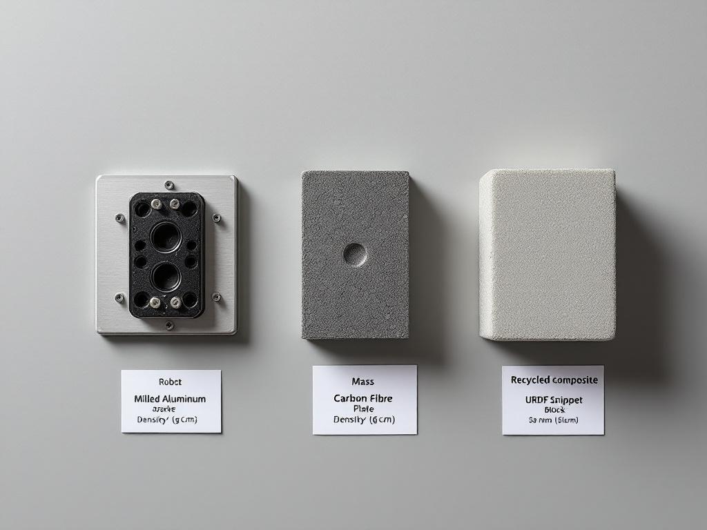
Material and Mass Optimization Inside the URDF File
URDF's <inertial> and <material> blocks are where URDF environmental impact gets committed. They look like ordinary technical fields, but each one is a sustainability decision encoded as XML. This section walks through a four-step workflow to use them deliberately.
Step 1 — Specify mass and inertia per link explicitly. The URDF <inertial> block syntax, documented in the ROS Wiki, looks like this:
<inertial>
  <origin xyz="0 0 0.05" rpy="0 0 0"/>
  <mass value="1.2"/>
  <inertia ixx="0.001" ixy="0" ixz="0" iyy="0.001" iyz="0" izz="0.0008"/>
</inertial>
For a real link, mass must come from material density multiplied by intended volume. Forcing the designer to fill this in means choosing a density value, which means choosing a material, before the simulation runs. The blank field is the design discipline.
Step 2 — Reference materials by name and define them once. URDF supports a <material> block such as <material name="aluminum_6061"><color rgba="0.8 0.8 0.8 1"/></material>. Designers can extend this convention with sibling XML comments or custom tags to record density, recyclability, and origin. The Automatic Addison mobile robot URDF example shows the standard material reference pattern in a working file. Defining materials once and referencing them by name across links keeps substitution clean — change the definition, every link picks it up.
Step 3 — Iterate material alternatives in the file, not in CAD. The workflow: change the density value in the inertial block, re-run the simulator (Gazebo, PyBullet, Drake), check whether the dynamics still meet performance targets. Compare at least three candidates per high-mass link. The file edit takes seconds. The simulation takes minutes. This is the loop CAD-first workflows cannot replicate cheaply.
Step 4 — Lock the choice with a comment trail. Use XML comments to document why a material was selected:
<!-- Material: recycled aluminum 6061. Selected over carbon fiber:
     comparable stiffness for this load case, lower embodied energy,
     local supplier (within 500 km). Substitution log: see rev 4 notes. -->
The comment travels with the file. When a new engineer joins the project two years later, the rationale is in the source, not in someone's archived email.
Material Optimization Checkpoint
- Mass declared per link from material density × volume — not estimated
- Inertia tensor computed (not zeroed out as a placeholder)
- At least three material candidates evaluated for each high-mass link
- Simulation passes performance baseline at chosen mass
- Material choice rationale documented in URDF comments
- Density values match supplier datasheets, not generic libraries
One caution worth stating directly: URDF does not validate that your declared mass matches a real material's actual density. It accepts any number you type. The format trusts the designer. The checklist exists because that trust has to be earned by discipline, not by tooling. Sustainable robot development depends on declared values being honest values.
Designing for Disassembly Through URDF's Joint Grammar
URDF cannot describe a welded multi-part body as a single rigid weldment without losing the connection information. Every multi-part structure must be expressed as links connected by joints. Even <joint type="fixed"> — a non-moving connection — is still a named, declared interface between two parent and child links. This grammatical fact is what makes URDF useful for circular-economy thinking.

Design for Disassembly (DFD) is an established practice in sustainable manufacturing: structure products so they can be taken apart non-destructively at end-of-life for repair, refurbishment, or material recovery. DFD requires explicit, accessible interfaces between parts — exactly what URDF's joint grammar produces. The connection between DFD as an engineering discipline and URDF as a description format is not coincidental; both demand that interfaces be declared rather than implied.
Walk through the joint types and what each implies for disassembly:
- Revolute and continuous joints describe rotational interfaces. In hardware, these correspond to bearings and rotary actuators — typically the most modular and replaceable subsystems on a robot.
- Prismatic joints describe linear interfaces such as rails or telescoping segments. Also typically modular by nature, since linear motion requires accessible bearing surfaces.
- Fixed joints are where DFD attention should focus. A fixed joint in URDF means "this link is rigidly attached to that link." In hardware, that translates to one of: bolts, snap fits, adhesives, or welds. The sustainability question for every fixed joint is the same: what fastener method realizes this in physical form, and is it tool-accessible?
A robot URDF that uses many fixed joints between small links is signaling lots of mechanical interfaces. That is good for DFD if those interfaces are bolted or snap-fit, bad if they are bonded or welded. URDF itself does not specify the fastener method — but it surfaces every place a fastener choice has to be made. That visibility is the contribution.
Modularity is not bolted onto URDF. It is the grammar. Every joint you declare is a disassembly point you can defend.
Consider an industrial 6-axis arm described in URDF. It will have at least six revolute joints (the actuated axes) and typically many fixed joints between motor housings, structural links, and end-effector mounts. If each fixed joint is realized as a bolted flange, a technician can swap any segment for repair or upgrade. If they are welded, the entire structural section becomes one disposable assembly. The URDF tells you how many decisions you have. The mechanical detailing tells you which choice you made for each.
Modular topology scales across product families. The curated awesome-robot-descriptions and awesome-urdf repositories show URDF files for dozens of robot families, and standardized link interfaces — consistent bolt patterns, electrical connector positions, common mounting flanges — appear repeatedly across them. Reusing link templates across robot variants reduces tooling investment, simplifies spare-parts inventory, and makes refurbishment paths predictable.
URDF allows custom XML comments and, in some toolchains, custom XML namespaces. Designers can attach maintenance metadata directly to joints:
<joint name="elbow_joint" type="revolute">
  <!-- Service interval: 5,000 hours
       Bearing replacement: SKF 6203, tool-accessible via M5 bolts
       Disassembly: remove cover, no adhesive
       End-of-life: bearing recyclable, housing aluminum 6061 -->
  <parent link="upper_arm"/>
  <child link="forearm"/>
  <axis xyz="0 0 1"/>
  <limit lower="-2.96" upper="2.96" effort="150" velocity="3.14"/>
</joint>
The honest limit: URDF doesn't enforce that fixed joints map to bolts rather than welds. The CAD team makes that call downstream. But URDF produces the list of every interface that needs that decision — turning a vague "design for disassembly" intention into a concrete enumeration of N joints that each require a documented choice. That enumeration is the difference between a DFD principle on a slide and a DFD review on a Tuesday morning. URDF eco-friendly robots are built joint by joint, and the joints are already named in the file.
When each joint carries documented service and disassembly notes, end-of-life decisions become tractable. A recycler reading the URDF metadata knows which segments separate cleanly. A refurbisher knows which subassemblies are swappable. The kinematic description has quietly become a maintenance and recovery manual — without leaving the engineering substrate where the design lives.
Simulation-Driven Waste Reduction with URDF and Physics Engines
URDF integrates directly with physics simulators — Gazebo, RViz for visualization, PyBullet, Drake, NVIDIA Isaac Sim. The same <inertial> and joint dynamics fields that describe the robot also drive the simulation. The Nav2 URDF setup guide documents the file-to-simulator handoff, and ROS2 URDF crash course material walks through the same workflow for ROS2. The implication for green robotics design is direct: a designer can stress-test mechanical assumptions before any part is cut, and over-engineered components show up as wasted mass that simulation no longer needs.
| Design Issue | How CAD Workflow Catches It | How URDF + Simulator Catches It | Material/Time Implication |
|---|---|---|---|
| Over-specified wall thickness | Often missed until prototype | Simulator shows performance margin; reduce mass and re-test | Avoids machining excess material |
| Oversized actuator | FEA on individual component | Full-system dynamic simulation reveals torque margin | Smaller motor = less rare-earth content |
| Unnecessary structural stiffness | Detected via prototype vibration | Joint damping/friction surface stability without extra mass | Avoids steel-where-aluminum-fits |
| Redundant sub-assembly | Functional review meeting | Removing the link in URDF reveals if it was load-bearing | Eliminates parts from BOM |
| Joint friction over-spec | Hard to test pre-build | Friction parameters reveal energy loss in simulation | Lower operating energy over service life |
The URDF + simulator loop is qualitatively different from CAD-based FEA. CAD FEA validates a component in isolation under defined loads. URDF + simulator validates the whole robot in motion — you see how a heavier upper arm propagates loads down through the shoulder, base, and floor mounting. This system-level view exposes mass that exists "just in case" rather than for a documented load case. Mass added without a justifying simulation result is, by definition, unjustified mass.
Iteration economics flip the design culture. Editing a URDF mass value and re-running a 30-second dynamic simulation is dramatically cheaper than re-machining a prototype bracket. In practice, this compresses the material-elimination loop from weeks (prototype-to-prototype) to hours (simulation-to-simulation). The discipline that benefits most is the willingness to try removing a part rather than only adding margin to existing parts. When the cost of asking "do we need this link at all?" drops to a five-minute file edit, the question gets asked more often.
There is a caution worth being direct about: simulator results are only as accurate as the URDF's declared properties. If a designer pads inertia values "to be safe," the simulation rewards over-engineering by passing every test. If joint friction is set to zero because nobody measured it, the simulation underestimates energy consumption. The discipline is to declare honest values — measured or sourced from datasheets — and trust the simulation to find the genuine waste. Defensive padding turns the simulator into a confirmation tool rather than a discovery tool, and the URDF environmental impact advantage evaporates.
Embedding a Sustainability Audit Trail in URDF Metadata
The largest practical risk to a sustainability strategy is handoff loss. A designer's intent — "I chose recycled aluminum because the supplier provides chain-of-custody documentation and is within 500 km" — disappears the moment the file is exported to STEP and emailed to manufacturing. URDF's text format and XML comment support let designers attach this intent directly to the structural description, so it travels with the file across every handoff.
The metadata pattern looks like this:
<link name="forearm">
  <!-- SUSTAINABILITY METADATA
       Material: Aluminum 6061-T6, 80% recycled content
       Supplier: [Name], ISO 14001 certified
       Embodied carbon: tracked in attached LCA sheet rev. 3
       End-of-life: fully recyclable, no coatings
       Service interval: 10,000 hours
       Disassembly: M6 bolts, no adhesive
       Substitution log: carbon fiber rejected (rev 2, embodied energy)
       Signoff: J.M. 2024-06-12 -->
  <inertial>
    <mass value="0.85"/>
    <inertia ixx="0.0008" ixy="0" ixz="0" iyy="0.0008" iyz="0" izz="0.0004"/>
  </inertial>
  <visual>...</visual>
</link>
URDF Sustainability Metadata Checklist
- Material origin recorded. Specify virgin vs. recycled content percentage. Note the source supplier and country.
- Supplier environmental certifications listed. ISO 14001 (environmental management), ISO 14040 (lifecycle assessment compliance), or equivalent regional certifications.
- End-of-life pathway declared. Recyclable, refurbishable, or hazardous-disposal-required. Note any coatings or composites that complicate recycling.
- Service interval and consumables identified per link. Hours of operation between service events; bearings, seals, or wear parts that will need replacement.
- Disassembly notes attached to fixed joints. Fastener type and tool requirements. Flag any adhesive bonds explicitly — they are the disassembly blockers.
- Embodied energy or carbon estimate referenced. Even a qualitative band (low/medium/high) is more useful than nothing. Link to an external LCA sheet by revision number.
- Substitution log maintained. Comment-trail of materials evaluated and rejected, with reasoning. This protects future designers from repeating dead ends.
- Review signoff captured. Initials and date of sustainability lead approval, in comments. Pairs with Git history for full attribution.
Tooling and integration matter as much as the metadata format itself:
- Custom XML namespaces. Some URDF toolchains tolerate non-standard XML tags; advanced teams define a
<sustainability>block alongside<inertial>. Verify your simulator parses it without error before committing to the convention across a project. - Git as audit substrate. Because URDF is plain text, every change to a metadata block is captured in
git blame. Sustainability decisions become attributable across years and across team turnover. This is something binary CAD files cannot offer cleanly. - Spreadsheet and dashboard exports. Simple parsing scripts can extract URDF metadata and emit a per-link sustainability summary for procurement and compliance review — no specialized PLM seat required. A Python script of under 100 lines can produce a clean CSV from a URDF tree.
- Standards alignment. The data fields above are designed to feed an ISO 14040-style lifecycle assessment input table. URDF metadata is the engineering substrate; LCA software does the calculation.
Good sustainable robot development practice treats the URDF file as the canonical design document, not just a simulation input. When the URDF is the canonical record, sustainability decisions get reviewed every time the file is reviewed, which in a well-run project is on every pull request.
Environmental Tradeoffs URDF Forces You to Confront
Eco-design is not a single-axis optimization. Lighter is not always greener. Faster is not always more efficient. Local is not always lower-impact. URDF's strength is that it forces the designer to declare values for each axis — mass, joint dynamics, motion limits, material — so the tradeoffs become visible. Five tradeoffs show up directly in URDF parameters and deserve to be confronted explicitly when designing for minimal environmental impact.
- Carbon-intensive lightweighting vs. heavier-but-lower-impact materials. Carbon fiber composite has excellent stiffness-to-weight, which appears as low mass in
<inertial>. But its production is energy-intensive, and end-of-life recycling pathways are limited; multi-layer laminates are particularly difficult to separate. Recycled aluminum may declare a higher mass value but carries lower embodied energy and recycles cleanly back into the same alloy stream. URDF makes the mass tradeoff numerical — you can see the kilograms — but the lifecycle tradeoff requires the metadata pattern from the previous section. Mass alone misleads. - Direct-drive actuators vs. geared lightweight motors. A direct-drive design declares larger actuator masses in URDF but eliminates gearbox losses, lowering operational energy consumption over the robot's service life. A geared design declares lower link mass but adds gearbox friction (visible in joint dynamics fields) and gearbox wear parts (visible in service metadata). The right answer depends on duty cycle. A robot running 16 hours a day weights operational efficiency much more heavily than a robot running 1 hour a day. The URDF makes both regimes simulatable; the sustainability target dictates which simulation matters more.
- Cycle speed vs. peak power demand. Aggressive joint velocity and acceleration limits in URDF unlock faster cycles, but they require larger actuators, larger drives, and larger upstream electrical infrastructure. Faster does not equal greener when peak power forces a battery oversize or facility supply upgrade. Run the simulation at multiple speed targets and compare energy-per-cycle, not just cycles-per-hour. The cheapest watt is the one the robot does not need to draw at peak.
Optimizing for weight alone hides a heavier environmental cost downstream. URDF makes you declare what you are optimizing for and measure it.
- Durability vs. recyclability. A composite link lasts longer (lower replacement frequency over the product's lifetime) but may be a multi-material laminate that cannot be separated for material recovery. A simpler aluminum link recycles cleanly but may need replacement sooner under heavy duty cycles. The sustainability metadata block should declare both expected service life and end-of-life pathway so the tradeoff is explicit. Hiding it behind a single "this material is more sustainable" claim is exactly the failure mode URDF helps avoid.
- Local sourcing vs. supplier environmental rigor. A nearby supplier reduces shipping carbon but may operate under weaker environmental standards or have less rigorous waste management. A distant ISO 14001-certified supplier may have lower per-unit lifecycle impact despite the shipping leg. URDF metadata should record both supplier location and certification status — the procurement team makes the call with the data visible rather than relying on a single dimension of "local is better" or "certified is better."
URDF does not resolve these tradeoffs. It surfaces them. The format's discipline is that you cannot leave a link's mass undeclared, which means you cannot leave the underlying material-and-energy tradeoff unexamined. This is the difference between a design culture that quietly defaults to convenient choices — whatever was easiest in CAD, whatever the rendering library defaulted to — and one that documents and defends each choice in a reviewable file. The latter is auditable. The former is not. Sustainable robot development is mostly a question of which culture your tooling encourages.
A URDF Eco-Design Workflow You Can Run on Your Next Robot
This is the operational sequence. Run it end-to-end on a real robot project. Each step produces an artifact — a file, a comment block, a simulation run, a parsed report — that feeds the next step. By Step 8, you hand CAD a constraint-rich URDF, not a wishlist of intentions.

Step 1 — Define environmental targets before any structure. Write down four numbers (or qualitative bands where numbers aren't yet available): total mass budget, embodied carbon ceiling, recyclability target as a percentage of mass that must be recoverable at end-of-life, and operational energy per cycle. These become acceptance criteria for the URDF. Without them, the rest of the workflow optimizes against nothing, and "more sustainable" remains a feeling rather than a result.
Step 2 — Sketch the link/joint topology. Draw the kinematic tree on paper or whiteboard. Mark every joint, including fixed ones. Each joint is a future disassembly decision. Aim for a topology where high-wear parts are on the leaves of the tree (end-effectors, sensor mounts), not buried in the structural trunk. Leaf-positioned wear parts are dramatically easier to service.
Step 3 — Write the URDF skeleton with placeholder properties. Create the XML structure with link and joint names, parent/child relationships, and joint types. Fill <inertial> blocks with placeholder masses marked TODO in comments. This produces a reviewable artifact in hours, not weeks, and lets non-CAD reviewers (procurement, sustainability, supply chain) weigh in before geometry is committed.
Step 4 — Populate inertial and material properties. Replace placeholders with values derived from real material density multiplied by intended geometry volume. Add <material> references. Begin the sustainability metadata block on each link using the eight-item checklist from earlier in this article.
Step 5 — Run dynamic simulation against performance targets. Launch in Gazebo, PyBullet, or your preferred simulator. The Nav2 URDF setup guide and ROS2 URDF crash course document the file-to-simulator handoff in detail. Verify the robot meets functional requirements. Record energy-per-cycle, peak torque per joint, and any margins observed.
Step 6 — Material iteration loop. For each link contributing more than roughly 10% of total mass (a useful rule of thumb), test at least two alternative materials by editing density and re-running simulation. Keep the substitution log in URDF comments — both selected and rejected materials, with reasoning. Future revisions benefit from the log; nobody re-evaluates carbon fiber three times.
Step 7 — Disassembly review. Walk through every fixed joint in the URDF. Document the intended fastener method (bolt size, snap fit, mechanical interlock) in the joint's comment block. Flag any joint that cannot be specified as non-destructively separable. These flags are the items to escalate to mechanical design before CAD detailing locks in welds or adhesives.
Step 8 — Generate the sustainability brief and hand off to CAD. Parse the URDF metadata into a one-page summary: total mass, material list with sourcing and certifications, recyclability percentage, service intervals per link, and a disassembly diagram derived from the joint tree. This brief travels with the URDF and STEP files into CAD detailing — making the environmental constraints non-negotiable inputs, not late-stage suggestions that get value-engineered out.
The URDF Eco-Design Checklist
- Environmental targets defined (mass, carbon, recyclability, energy/cycle)
- Link/joint topology sketched with disassembly logic in mind
- URDF skeleton committed to version control
- Mass and inertia declared per link from real density data
- Material
<material>blocks defined and referenced consistently - At least two material alternatives evaluated for each high-mass link
- Dynamic simulation passes performance baseline
- Sustainability metadata block populated on every link
- Every fixed joint has a documented fastener method
- Sustainability brief generated and attached to CAD handoff
If your current URDF file has empty <inertial> blocks, undocumented fixed joints, or no material metadata, you have not finished the design. The format is telling you what is missing. The fields are blank because the decisions are not made. Fill them in before geometry locks them in for you.