
From Arduino Robot Kit to ROS 2: Bridging Hobby Robots with URDF Simulation
Your Arduino Robot Kit Works—Now It's Time to Make It Simulate
You assembled the chassis in an afternoon. Two DC motors, an L293D driver, a 9V battery feeding the Arduino's onboard regulator, and a sketch that handles forward, back, left, right. The 15-minute build tutorial made it look easy because it is. But the arduino robot kit sitting on your workbench has now hit the wall every hobbyist hits: you want encoders, sensor fusion, a learned policy, or a planner that can avoid an obstacle without you scripting every reaction. Every new behavior risks a gear strip. Every bug gets paid for in burned servos.
The typical hobby arm makes this worse. Most run 5–6 DOF on SG90 or MG996R servos with no position feedback, per Ken McElhinney's 6-DOF arm build and the PCB HERO 5-DOF SG90 walkthrough. Open-loop actuators plus iterating on physical hardware is a recipe for spending more time soldering than coding.
By the end of this article you will know how to do four things: audit your existing arduino robot kit for the measurements URDF requires, author a URDF at the right fidelity level for your goals, choose between Gazebo and Isaac Sim without wasting a weekend on the wrong one, and package the result as a reusable ROS 2 description package. URDF Hub maintains 50+ peer-reviewed reference models — UR5e, TurtleBot3, Franka Panda, KUKA iiwa 14, Spot — that you can study while you build your own.
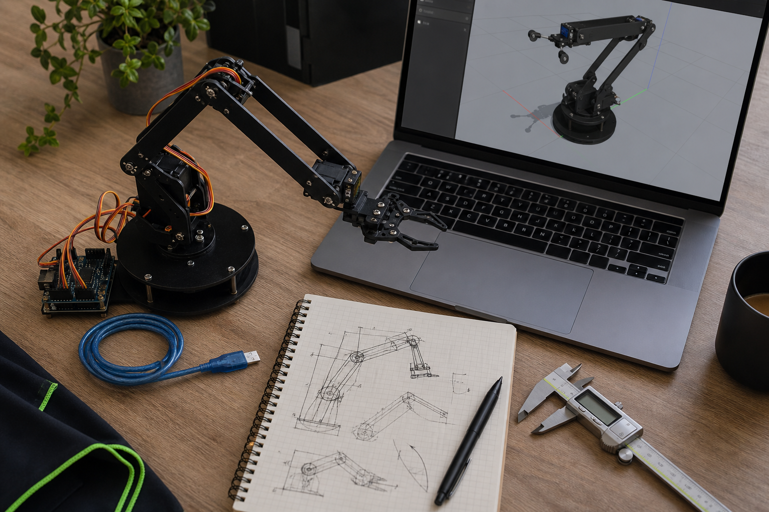
Table of Contents
- Why Your Arduino Robot Kit Hits a Ceiling Without a Digital Twin
- The 7-Step Audit That Turns Your Arduino Kit Into URDF-Ready Measurements
- Choosing Your URDF Fidelity Level: Skeleton, Detailed, or Photo-Real
- Authoring the URDF: Raw XML, XACRO Macros, or CAD Export
- Gazebo vs. NVIDIA Isaac Sim: The Choice That Defines Your Workflow
- Closing the Sim-to-Real Gap When Your URDF Meets the Arduino's Open-Loop Servos
- Packaging Your URDF as a Reusable ROS 2 Description Package
Why Your Arduino Robot Kit Hits a Ceiling Without a Digital Twin
Hardware-only development has three hard limits, and each one bites at a predictable point in your project's lifecycle. Recognizing them early lets you decide whether the ROS 2 + URDF investment is worth it for your arduino robot kit or whether you should keep the build simple.
Iteration cost on physical hardware. Every code-test cycle on hardware burns minutes and, eventually, servos. The SG90s used in nearly every hobby arm — and documented in the PCB HERO 5-DOF tutorial — have short MTBF under repeated stall conditions. A typical debug cycle looks like this: write code, upload via USB, watch the arm collide with the table, hear the plastic gear strip, spend 30 minutes swapping servos, re-zero the joints, try again. A physics step in Gazebo completes in under 5 milliseconds. You can run hundreds of failure cases in the time it takes to disassemble a single servo horn.
Architectural coupling. A pure Arduino sketch stuffs perception, planning, and actuation into one file. The 15-minute robot tutorial is the canonical example: forward, back, left, right all live as branches in a single loop() function. That works until you want a behavior tree, a SLAM stack, or anything that doesn't fit in 32KB of flash. ROS 2 separates concerns: the Arduino becomes a thin PWM and encoder layer driving motors from pins D5/D6 and D9/D10, while planning, perception, and behavior run on the host PC. The Construct's Building Your 1st ROS 2 Robot series demonstrates exactly this split.
No path to learned behaviors. Reinforcement learning needs thousands of episodes per hour. Open-loop servos cannot survive that. Simulation is the only feasible substrate for any policy-learning work, and a URDF is what makes the simulator's robot match the physical one.
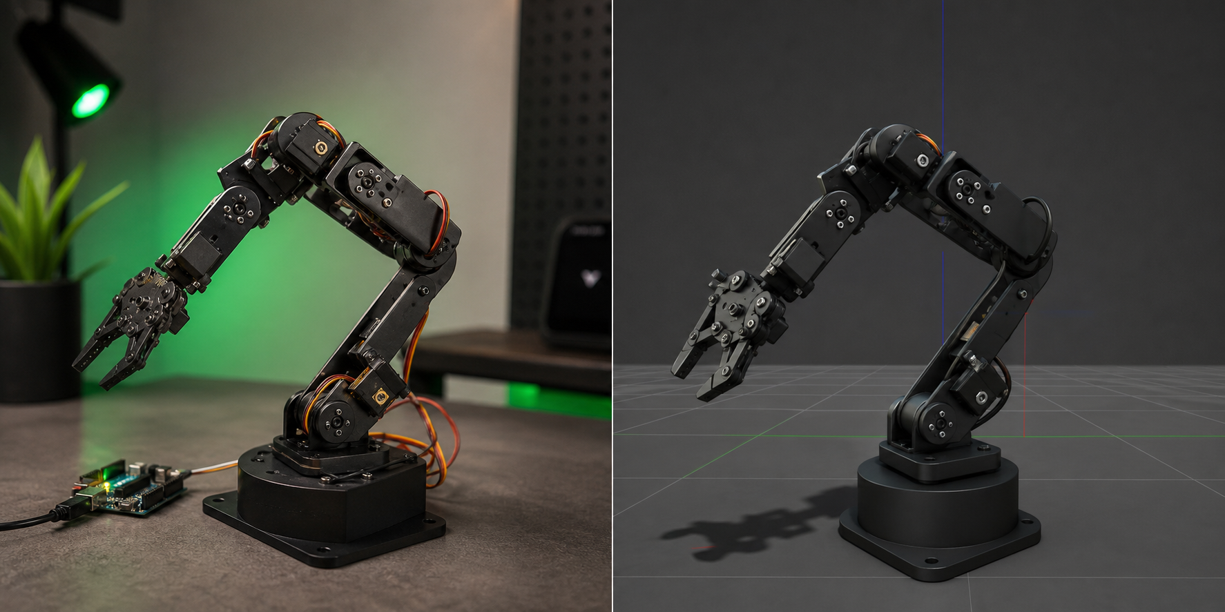
The architectural shift is this: the Arduino becomes a dumb peripheral exposing motor commands and encoder reads via rosserial — 115,200 baud in the PCB HERO pipeline, 57,600 baud in The Construct's series — and the URDF becomes the contract between physical and virtual. It declares geometry, joints, inertials, and collision meshes in a form that RViz, Gazebo, MuJoCo, PyBullet, and Isaac Sim all consume.
Simulation does not replace hardware testing. It eliminates the two hundred failed hardware tests you no longer need to run.
The honest counter-argument: if your robot only drives forward, back, left, right under manual control, ROS 2 plus URDF is overkill. The 15-minute Arduino chassis works fine without any of this. The investment makes sense when you need modularity, sensor fusion, motion planning, or learning. If you're building a desk toy, stay in the Arduino IDE. If you're building anything that needs to perceive its environment or plan its next action, keep reading.
The 7-Step Audit That Turns Your Arduino Kit Into URDF-Ready Measurements
Most hobbyists never write down the dimensions, masses, and joint limits of their robot. URDF demands all of them in SI units. Vague measurements produce simulations that diverge from hardware behavior, and that divergence shows up later as inverse-kinematics failures in MoveIt — exactly the failure mode documented in The Construct's DIY arm forum thread. Spend the time now or spend it later, doubled, in the debugger.
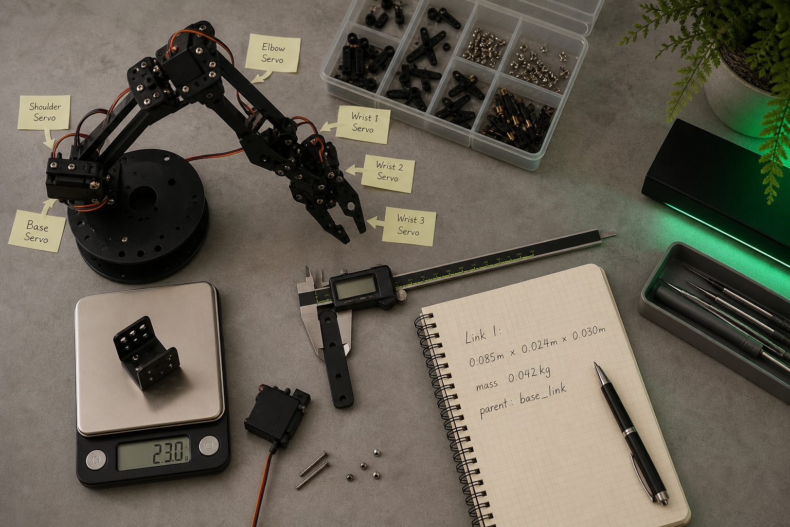
- Map the kinematic chain. Sketch the parent-to-child relationships starting from
base_link, which is the ROS convention used in the ROS 2 URDF tutorial. For a 4-DOF arm:base_link→shoulder_link→upper_arm_link→forearm_link→gripper_link. Draw it on paper before you open a text editor. - Measure link dimensions with calipers. Length, width, height in meters. URDF uses SI units throughout, and millimeter slop in joint origins compounds across a 5-DOF chain. For servo-driven arms, measure servo-horn to servo-horn distance — that's the kinematic length — not the outer dimension of the printed bracket.
- Weigh or calculate link mass. A kitchen scale with 1-gram resolution is sufficient at hobby scale. For 3D-printed parts you don't want to disassemble, use volume × material density: PLA is 1.24 g/cm³, PETG is 1.27 g/cm³. Get inertia in the ballpark; perfectionism here is wasted effort.
- Identify joint types and limits. SG90 servos provide roughly 180° of travel. MG996R units provide about 120°. Read the datasheet for your specific batch, then derate by 10° on each end for mechanical safety. Map each one to a URDF
revolutejoint with explicit<limit lower="" upper="" effort="" velocity="">tags, following the pattern in Ken McElhinney's servo arm build. - Locate joint origins in the parent frame. This is the most common URDF mistake by a wide margin: the
<origin>of a joint is expressed in the parent link's coordinate frame, not the child's. Get this wrong and your robot will appear inside-out or scattered across the world origin in RViz. - Document sensor placements. Camera position and orientation relative to
base_link. IMU mounting offset. Encoder presence or absence — and note that SG90-class servos have no feedback at all, which becomes the central constraint in any later planning work. - Photograph and label. Annotate the photos with the exact link names you'll use in your URDF (
link_3,shoulder_joint,gripper_finger_left). Future-you will not remember whatlink_3was three months from now.
Budget two to three hours for a 5–6 DOF arm. That's the most common configuration across hobby Arduino arm kits, per both McElhinney's build and the PCB HERO walkthrough. Mobile bases take less — usually under an hour if the chassis is a simple two-wheel differential drive.
Choosing Your URDF Fidelity Level: Skeleton, Detailed, or Photo-Real
URDF authors face a tradeoff between fidelity and simulation speed. The official ROS 2 URDF tutorial deliberately uses simple primitives — boxes, cylinders, nominal inertias — to keep iteration fast. This is not laziness. It is correct first-pass practice, and skipping it costs you days you didn't budget for.
| Layer | Visual Geometry | Collision Geometry | Authoring Time | When to Use |
|---|---|---|---|---|
| L1: Skeleton | Box/cylinder primitives | Primitives | 2-4 hours | Kinematics check, RViz validation, RL training |
| L2: Detailed | Primitives + simple meshes | Simplified meshes | 1-2 days | Gazebo physics, manipulation, sensor dev |
| L3: Photo-real | Full CAD per link | Detailed mesh decomposition | 3-5 days | Final validation, digital twin, demos |
A perfect URDF built from sloppy measurements is still a sloppy URDF. Calipers now, or debugger later.
L1 — Skeleton mirrors the ROS 2 official tutorial pattern. Boxes for links, cylinders for wheels, primitive collision shapes. It catches roughly 80% of the bugs you'll ever encounter — wrong joint axes, swapped parent/child links, joint limits that exceed mechanical reality, mass values off by an order of magnitude. It runs fastest in RViz, loads in under a second, and lets you iterate on the kinematic structure without committing to mesh geometry. Start here. Always.
L2 — Detailed is the default fidelity for most published URDF Hub models. TurtleBot3, UR5e, Franka Panda all ship at this level: collision-critical links use simplified meshes (decimated to a few hundred triangles), visual links use primitives or low-poly meshes, sensors are modeled with explicit plugins. This is the sweet spot for Gazebo physics. Friction coefficients, contact normals, and inertial tensors all behave predictably at this fidelity.
L3 — Photo-real is for validation, not for iteration. Full CAD meshes with PBR materials look impressive in screenshots and slow physics step time by a factor that matters when you're running hundreds of episodes per minute. They also risk overfitting your simulation to CAD geometry that doesn't match the as-built robot — your real link has burrs, a slightly-warped 3D print, and a screw head sticking up 2mm. Use L3 for final demos and digital twins where appearance is the deliverable.
The hard rule: start at L1, escalate only when behavior diverges from hardware in a way that geometry can explain. The DIY arm thread on The Construct demonstrates this clearly — an accurate L2 URDF still cannot rescue MoveIt trajectories when the hardware has open-loop SG90 servos with mechanical play. Fidelity above L2 rarely solves a problem that better hardware wouldn't.
Authoring the URDF: Raw XML, XACRO Macros, or CAD Export
URDF is verbose XML. XACRO — a macro preprocessor — cuts repetition but adds an abstraction layer. CAD exporters generate URDF automatically but produce messy output that almost always needs manual cleanup. Choose your authoring approach based on robot complexity and how much repeated structure you need to express.
If your arduino robot kit has ≤6 DOF and no repeated structures (typical 5-6 DOF servo arm). Use raw URDF in a text editor. Start by copying a similar URDF Hub model — TurtleBot3 Burger for mobile bases, a published servo-arm model for manipulators — and modify the link and joint blocks. Validate with the check_urdf command before loading into RViz or Gazebo. The ROS 2 URDF tutorial walks through this stepwise: add the base, add wheels, add joints, add inertials. Forty-five minutes from copy to working RViz visualization is reasonable.
If your robot has repeated structures (4 identical wheels, 5-link snake, parallel grippers). Use XACRO. Define the repeating unit once as a macro, instantiate it N times with parameters. XACRO compiles to URDF at launch time via xacro robot.urdf.xacro > robot.urdf. This is also how most URDF Hub models are distributed — the XACRO source is included so contributors can re-parameterize them for their specific hardware (different wheel radii, different arm reach).
If you have CAD files (STEP, SolidWorks, Onshape). Use a CAD-to-URDF exporter. The SolidWorks-to-URDF plugin, the Onshape exporter, and Fusion 360 plugins all exist and all work — within limits. Export collision meshes as STL with reduced polygon counts (under ~5,000 triangles per mesh for Gazebo performance). Ken McElhinney's 6-DOF arm workflow demonstrates exactly this pipeline: build the 3D model, derive the URDF, load it in RViz with roslaunch urdf_tutorial display.launch model:=arm.urdf. Expect manual cleanup — exporters get geometry right but joint axes, limits, and inertial frames frequently wrong.
Red flags and common gotchas. Mesh paths must use package://my_robot_description/meshes/link.stl, never absolute filesystem paths — relative paths break the moment you share the package or move it between machines. The <origin> tag inside a joint is expressed in the parent link's frame; if your robot renders inside out, this is almost certainly the cause. Always run check_urdf before launching Gazebo — Gazebo's error messages on malformed URDFs are nearly unreadable and will eat hours. If you're using rosserial to talk to the Arduino, hard-code the baud rate (115,200 in the PCB HERO pipeline, 57,600 in The Construct's tutorial) and document the expected /dev/ttyUSB# or /dev/ttyACM# device. Serial port drift across reboots is a recurring source of "why won't my robot move" tickets.
Gazebo vs. NVIDIA Isaac Sim: The Choice That Defines Your Workflow
Both simulators consume the same URDF. Workflow friction differs by an order of magnitude. Pick the wrong one for your goal and you spend weeks fighting tooling instead of solving the actual problem.
| Criterion | Gazebo (Classic / Harmonic) | NVIDIA Isaac Sim |
|---|---|---|
| Physics Engine | ODE / Bullet / DART | PhysX (GPU-accelerated) |
| Parallel Simulations | Single-process CPU | GPU batch (RL training) |
| Rendering | OGRE, basic shading | RTX path-tracing, PBR materials |
| Hardware Requirement | CPU + modest GPU | NVIDIA RTX-class GPU required |
| Learning Curve | Lower; broad ROS 2 community | Higher; Omniverse + Python API |
For Arduino-scale hobby robots and educational use, Gazebo wins by default. The ROS 2 tutorial ecosystem targets Gazebo or RViz. The community is larger, the documentation is denser, and the hardware barrier is minimal — an integrated GPU and 8GB of RAM is enough to get a 6-DOF arm running. Startup time is under 10 seconds; you can iterate.
Isaac Sim becomes the right call in two specific scenarios. RL training at scale: running thousands of parallel episodes per hour for policy gradient methods is feasible on PhysX/GPU; Gazebo's CPU physics cannot match this throughput. Photoreal sensor simulation: if you're training a vision model that will deploy to a real camera, PBR rendering in Isaac Sim narrows the visual sim-to-real gap meaningfully. Outside those two cases, the RTX GPU requirement and 20–60 second startup time are overhead you don't need.
McElhinney's servo-arm workflow and the canonical Arduino+ROS rosserial pipeline both validate kinematics in RViz first, then move to Gazebo for physics. This is the path to follow for any reader coming from an arduino robot kit. Start where the tutorials are.
Migration friction matters. Moving a tuned URDF from Gazebo to Isaac Sim requires re-tuning friction coefficients and joint damping — PhysX and ODE produce different contact dynamics, and values that gave you stable grasping in Gazebo will let objects slip in PhysX. URDF Hub models include physics tags that work in both simulators, but tuned values are not portable between them.
Decision rule: default to Gazebo. Migrate to Isaac Sim only when you hit a specific wall — training throughput or rendering fidelity. Do not start in Isaac Sim "to future-proof." You will spend the first month learning Omniverse instead of robotics.

Closing the Sim-to-Real Gap When Your URDF Meets the Arduino's Open-Loop Servos
Simulated robots and real robots disagree. The interesting question is where the disagreement lives and which parts of it the URDF can fix.
Modeled physics — URDF's domain. Gravity, link inertia, joint friction, joint damping. These are URDF tags. The ROS 2 tutorial demonstrates the minimum viable set: <inertial>, <mass>, <origin>. Tune these from your audit measurements. If your simulated arm sags more than the real one under gravity, your mass estimates are too high. If it sags less, they're too low. The fix is a number change in XML, not a hardware modification.
Sensor noise, latency, and quantization — not in URDF. Camera frame delay, IMU bias, encoder resolution. These live in sensor plugins or driver code, not in the URDF geometry itself. Gazebo's sensor plugins accept a <gaussianNoise> tag for deliberately injecting realistic noise into otherwise-perfect simulated sensors. But if your arduino robot kit uses SG90 servos with no feedback at all, there is no encoder to model — your simulation runs with perfect joint observation that your hardware fundamentally cannot provide. That asymmetry has to be addressed at the control layer, not by adding more XML.
Unmodeled effects — nowhere. Cable drag, gear backlash, servo dead-band, bearing stiction, thermal drift, mechanical resonance. The DIY arm forum thread documents this exactly: a user with an "accurate simple URDF" reports MoveIt trajectories that succeed in simulation but fail on hardware because the SG90s have mechanical play and no feedback to compensate for it. The diagnosis is correct. The URDF is not the problem. No URDF tag exists for "this 5-dollar servo has 3 degrees of backlash."
The key insight: a perfect URDF cannot compensate for poor hardware. But a bad URDF will fail loudly and early — joint angles won't match between sim and real, the reachable workspace will be wrong, collisions will happen where they shouldn't. Use simulation to catch the obvious bugs cheaply. Use hardware testing to catch the unmodeled effects that no simulator will ever predict.
A practical iteration loop that respects this division:
- Author the URDF assuming ideal physics — no noise, no friction beyond your audit values.
- Validate kinematics in RViz first. McElhinney's pipeline does exactly this: load URDF in RViz, manually move joints via
joint_state_publisher_gui, confirm geometry visually before any controller code exists. - Move to Gazebo for physics validation. Confirm the robot stands, walks, or reaches without exploding when gravity is applied.
- Bridge to hardware via rosserial at the documented baud rate (115,200 in the PCB HERO pattern, 57,600 in The Construct series).
- Compare measured joint positions to commanded positions on the real robot. If divergence exceeds about 5°, suspect mechanical play or open-loop drift, not URDF errors.
- Tune friction and damping in URDF only if the divergence pattern is systematic — for example, the arm consistently sags under load. That points to a mass or inertia value worth revisiting.
The sim-to-real gap is not a URDF problem. It is a sensor and actuator problem. Get the URDF correct first, then inject realism where the hardware actually fails.
What URDF Hub contributors offer that shortens this loop: verified collision meshes (so simulated collisions match real geometry), realistic joint limits derived from datasheets rather than theoretical maximums, and audited mass and inertia values. Each of those removes a debugging cycle you would otherwise run yourself.
Honest expectation-setting before you spend a weekend on this: do not promise yourself perfect sim-to-real transfer. The forum thread proves it can't be had with open-loop hardware. An accurate URDF plus SG90 servos still produces real-world failures because the hardware itself lacks the feedback channel needed to close the loop. The path to reliable transfer is URDF plus better actuators — Dynamixel servos with position feedback, encoders on DC motors, or closed-loop compensation in your control code. The URDF is necessary. It is not, by itself, sufficient.
Packaging Your URDF as a Reusable ROS 2 Description Package
A one-off URDF file is brittle. The mesh paths are wrong on someone else's machine, the launch files reference your home directory, and the only person who understands the joint ordering is you, on a Tuesday, having just touched the code. A properly packaged ROS 2 description package travels across projects, teammates, and simulators. The AntoBrandi "Robotics and ROS 2 Learn by Doing — Manipulators" repository demonstrates this pattern: the same arm description is reused across voice control, planning, and multiple controllers. Only the high-level nodes change.
- Create the package skeleton. Run
ros2 pkg create my_robot_description --build-type ament_cmake. The_descriptionsuffix is the ROS 2 convention and makes the package's purpose obvious in any workspace. - Add the directory structure. Create
/urdf,/meshes,/launch,/config, and/rviz. Keep visual meshes under/meshes/visualand collision meshes under/meshes/collisionas separate files — collision meshes should be lower-polygon copies of the visual ones, not the same file. - Author the URDF or XACRO. Place
robot.urdf.xacroin/urdf. Reference meshes withpackage://my_robot_description/meshes/visual/link.stl. Thepackage://URI scheme is what makes the package relocatable — anyone who clones your repo gets working paths automatically. - Write the display launch file.
display.launch.pyloads the URDF into therobot_state_publishernode, startsjoint_state_publisher_guifor manual joint manipulation, and opens RViz with a saved config. Mirror Ken McElhinney's pipeline: RViz first, Gazebo later. This launch file should work without any hardware connected. - Write the simulation launch file.
gazebo.launch.pyaccepts ause_sim_time:=trueargument, spawns the model in Gazebo, and starts the controller manager. Keep simulator-specific config in/config/gazebo.yamlso Isaac Sim, PyBullet, and MuJoCo variants stay separable in their own YAML files rather than tangled with shared parameters. - Write the hardware launch file.
hardware.launch.pystarts the rosserial node at the documented baud rate (115,200 per the PCB HERO pipeline or 57,600 per The Construct series), wires up/joint_statesand/cmd_veltopics, and broadcasts the static TF tree. Include the serial device path as a launch argument — never hard-code/dev/ttyUSB0, because it will be/dev/ttyACM0on someone else's machine. - Document the TF tree and joint names. Your README should list every link, every joint with its limits, the expected
/joint_statesordering, and known hardware constraints — for example, "shoulder_joint is open-loop SG90; expect ±3° tracking error." The DIY arm forum lesson is that undocumented hardware limitations break downstream MoveIt integration weeks later, when someone else inherits the project. - Test and publish. Run
ros2 launch my_robot_description display.launch.pyfor RViz, thengazebo.launch.pyfor physics, thenhardware.launch.pyagainst the real arduino robot kit. Push to GitHub. Submit to URDF Hub via the contribution process — verified models receive peer review, formal documentation review, and visibility to the broader community of researchers, students, and engineers looking for exactly the model you just spent two weeks building.
The reusability payoff is real. With this package structure, the same URDF drives Gazebo, Isaac Sim, PyBullet, MuJoCo, and the physical arduino robot kit on your bench. Your control nodes subscribe to /joint_states and publish to /cmd_vel or /joint_trajectory_controller/joint_trajectory regardless of where the robot lives — sim, hardware, or both running in parallel for comparison. The AntoBrandi repository demonstrates exactly this: controllers swap, description stays. Voice control, MoveIt planning, and manual teleop all consume the same description package; the URDF is the stable interface.
A final note for contributors: published model libraries welcome Arduino-kit submissions. Document the hardware spec, provide the URDF and meshes, test in at least Gazebo plus one other simulator, and submit. Maintainers verify and publish under MIT or Apache 2.0 licensing — your model becomes a reference for the next person standing exactly where you stood six months ago, looking at an arduino robot kit and wondering how to make it simulate.